Crypto WAV: Lab asssignment
Objective
The aim of this assignment is to design an efficient GPU implementation of an audio file encryption algorithm.
Audio encryption for dummies
Near the end of the last century (1980’s/1990’s) consumer TV decoders had limited processing capacities, that’s why audio encryption was particularly rudimentary. It simply reversed the spectrum by symmetry with respect to the zero-frequency axis. Here again, the original processing was analog. We’re going to make a digital adaptation that retains all its properties, in particular its characteristic sound signature:
Example of spectrum-flipped audio (dialogue from a movie)
Digital audio in a nutshell
A digital signal is a sequence of values defined at so-called sampling times and represented in a given format (8-bit or 16-bit, for example).
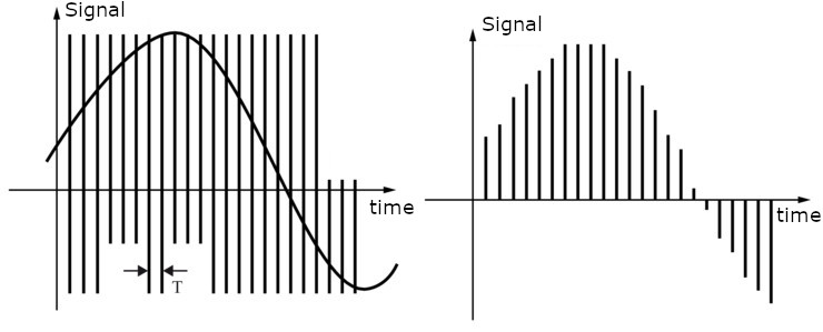
In most cases, the sampling instants are regularly spaced, so we speak of a sampling frequency \(F\), as in the figure below, which illustrates how an analog signal (left) is digitized with a sampling period of \(T = 1/F\) (right). In the case of audio, the sampling frequency historically used to burn CDs is \(F = 44100~Hz\), or 44100 samples per second. This value is related to the maximum bandwidth of the human ear, less than 20kHz.
Audio Encryption by Spectrum Reversal
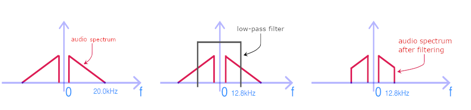
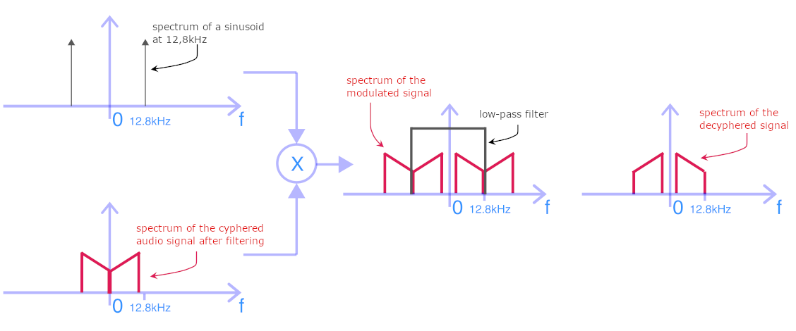
If we plot the frequency decomposition of an audio signal on a graph, which we call the spectrum, we could, for example, have the result of the figure on the left below. Since audio signals are conventionally sampled at \(F_{ECH}=44.1kHz\), the maximum allowed bandwidth is \(F_{ECH}/2\), i.e. around 22kHz, which is beyond audible to a homo-sapiens. To flip the spectrum, we start by passing the input signal through a low-pass filter, which will strongly attenuate or even suppress high frequencies, above 12.8 kHz in our case. The post-filtered signal thus presents a truncated spectrum, as shown in the following figure (right handside image).
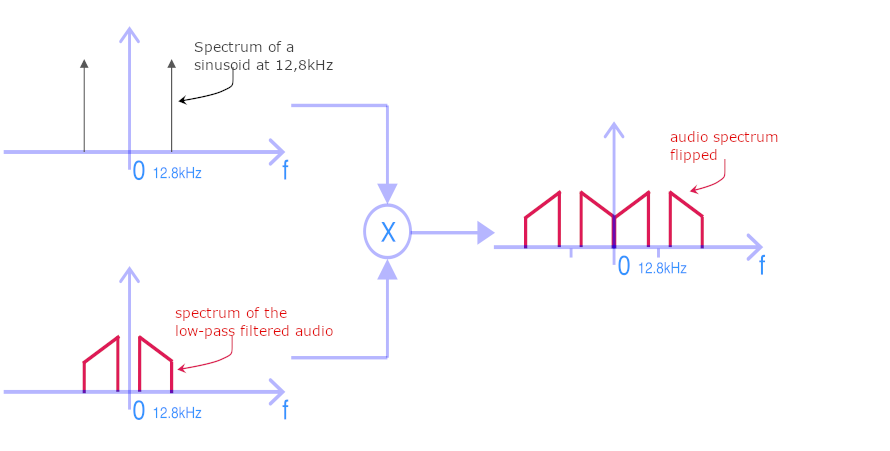
The filtered signal is then multiplied by a sinusoid of frequency 12.8kHz. This is called amplitude modulation. The spectrum of such a sinusoid is composed of two peaks at +/- 12.8kHz, as shown in the figure below. The result of multiplying the audio signal by a sinusoid is to shift the spectrum by +/- the frequency of the sinusoid (12.8kHz in our case). The result is shown in right handside image of the figure below. It can be seen that the initial spectrum between 0 and 12.8kHz has been reversed. The result is an audible signal that has nothing to do with the original and, in the case of speech or dialogue, is completely unintelligible.
Note
The spectrum of the input signal has first been truncated by the low-pass filter, which has suppressed/attenuated high frequencies. This has very little effect on the listening and sound as most of the energy and information is to be found below 10 kHz. Naturally, this may be noticeable in Hi-Fi listening, but TV broadcasting at the time (and still today) was a far cry from Hi-Fi quality. As a reminder, telephone bandwidth is only 300Hz-3kHz…
Decrypting a flipped-spectrum signal
Encryption was performed by multiplication with the sine wave at 12.8kHz. As the effect obtained is a spectrum shift of +/- 12.8kHz, decryption will use the same technique:
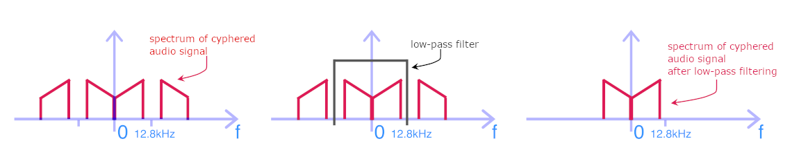
Low-pass filtering at 12.8kHz to eliminate high frequencies from the encrypted (returned) audio spectrum. The result is illustrated below.
Modulation (multiplication) with a sinusoid at 12.8kHz to shift the spectrum.
Low-pass filtering at 12.8kHz to eliminate high frequencies from the deciphered (re-flipped) audio spectrum. We can see that the spectrum shape has been put back in the right direction. It has not, however, recovered the high frequencies removed during encryption; what’s lost is lost.
Designing a digital low-pass filter
In discrete-time signal processing, low-pass filtering is performed by weighted averaging of a number of past samples of the input signal and possibly some of the output signal. The simplest technique is the finite impulse response (FIR) filter, which only need to integrate past samples of the input signal. Let (n) be the number of samples integrated into the average computation. Two properties then need to be taken into account:
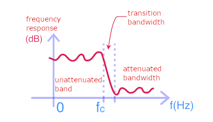
The filter’s desired steepness: this is the slope of its response diagram in the transition band. In the above illustrations of encryption and decryption methods, we’ve shown ideal filters with an infinite slope, but such filters are not feasible. The figure below shows the actual frequency response of a low-pass filter. The number of samples (n) will influence the steepness: the more coefficients you have, the stronger the averaging will be (the fewer high frequencies remaining); the filter will be stiffer.
The purity of the filter’s frequency response: The fact of observing the signal only over a limited time window defined by the number (n) mathematically generates unwanted oscillations in the filter’s frequency response and distorts the output signal. To mitigate these undesirable effects, a weighting is applied to the samples that make up the average. Weighting coefficients are obtained by evaluating suitable functions. Amongst all interesting functions, we can cite the Gaussian and the cardinal sinus, centered on the middle of the averaging window.
WAV File Format
wav (RIFF) is an older format but is still used because its design makes it quite versatile. The parameters of .wav files are stored in their headers, the contents of which are described HERE
As this project is about parallel computing, and not fundamentally audio processing, we will impose the following parameters in order to simplify the audio file management:
Format for storing audio data in the file: full PCM (code 1)
Number of channels: 1 (mono)
Number of bits per sample: 16
For this purpose, the libsndfile library (and its -dev version) has been installed on cluster1 and can be used to load and write .wav file. The reference documentation of libsndfile can be found here and a sample source code testLibsnd.cpp is also available.
The following inclusion is needed to use libsndfile in your own source code
#include <sndfile.hh>
To be able to run any program using libsndfile, it needs to be linked against the lib. That is achieved by adding the -lsndfile option to the C++ linker, like in the following compilation command example:
$> g++-9 testLibsnd.cpp -o testLibsnd -lsndfile
Warning
Two of the header fields are calculated from the size of the audio data. So one should not try write the header until they know the data to be written (or at least its size).
Audio data must be written in little endian form, i.e. writing the low byte first, then the high byte of each data item.
Instructions
You’re asked to design a program capable of:
Loading a clear or encrypted audio wav file from disk (using libsndfile library).
THEN depending on the command-line option
processing the audio signal on the GPU to make this audio unintelligible by flipping its spectrum.
OR
processing the audio signal on the GPU to make this audio intelligible by flipping its spectrum.
In either case: writing the resulting wav file on disk at the end (using libsndfile library).
The kernels that will process the audio signal should make the most of the GPU’s capabilities. The effective signal processing speed will be a major factor in the final grade.
You can either re-use the Nvidia template in the samples-etu/0_Simple folder or write your own source code from scratch. Whatever solution you take, remember that your code needs to perform the following:
allocate device memory
copy data from host memory to device memory
initialize thread block and grid dimensions
launch CUDA kernel(s)
copy result(s) from device to host
deallocate device memory
The excutable generated as a result of compiling the lab with the make command and the tuned Nvidia-provided Makefile, should be launched using the following command:
perrot@cluster1:~$ ./cryptoWav <cypher|decypher> -i <input.wav> -o <output.wav>
Note
As a reference, you can process this
Famous american song.The above .wav file has been converted to a mono (single channel) audio signal to simplify your life.
My own tests will include various files.
Your work will be graded according to several criteria:
the quality of the CUDA code
the answers to the following questions
the performance of your program
Questions
In addition to the code itself, you are requested to answer the following question, that will help in understanding your code design.
Were there any difficulties you had with completing the optimization correctly?
Which optimizations gave the most benifit?
How many global memory reads are being performed by your kernel(s)? explain.
If you used the shared memory, did you manage to avoid bank conflicts? How?
Warning
Deadline
You are invited to send me your source code via e-mail as an attachment. The subject must be [M1IoT CryptoWav].
I must receive your codes by Wednesday, December 13th. Any code that would not be sent by this date will receive a grade 0/20.
On the 15th of december, you will present your design during 5 minutes and then answer a few questions for 5 more minutes.